2/2023 – 3/2023
INTRO
This project was done as a test for my first PCB design, an led matrix. I designed the PCB in EasyEDA and got it fabricated by JLCPCB. I used 6 of these tiny matrices to create the hours, minutes, and seconds of a clock. The project is currently built on a breadboard for testing, but I later plan on making another pcb that would contain the RTC functions and processing all on one board.
PCB AND SCHEMATIC
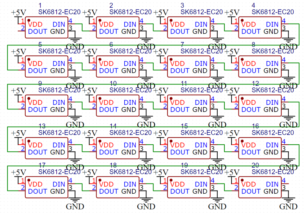
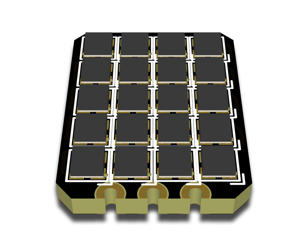
Here is the schematic and PCB design itself. Each of the LED’s is an addresable SK6813 chip that takes a data-in and puts a data-out. To power and address display what to show, the PCB takes 5V in and a data-in signal. To run of 6 of these, I used 6 GPIO pins on an Arduino Mega board. I could have daisy-chained these together, but having each one as a standalone unit made more sense to me and made it easier to code.
CODE
To actually show numbers on the led matrices, I numbered the led’s 0-19 and made a binary-like array that would turn on the respective LED’s to display numbers 0-9. This ended up working really well and made it easy to control.
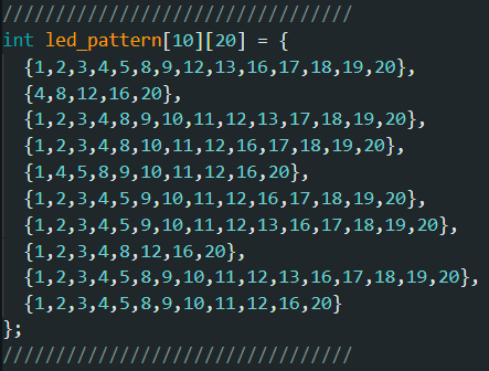
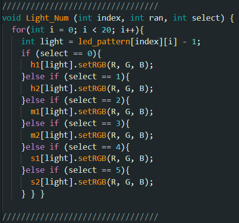
The Light_Num Function I wrote would take in the desired number, which panel you want to display on, and a color selector. This would pull from the led_pattern array and go through a loop to turn each of the LED’s on. Along with the code to drive the panels, I used a basic <DS3231.h> RTC library to keep the time as an integer, which would then be used to tell each of the panels what number to display.
FINAL
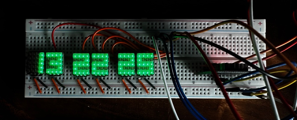
Here is the final look at the clock on a breadboard. While it is not finalized, I wanted to show how the clock looks in full operation. Each of the matricies can be configured to whatever color and style desired, the RTC on the right keeps perfect time and displays the exact time down to the second.
CONCLUSIONS
This ended up being a super fun project that taught me the basics about designing my first schematics and PCB. I hope you enjoyed the project.
