1/2024 – 3/2024
INTRO
I’ve been working on a research project for the past 3 months with one of my EECE professors, John Lund at Western Washington University. Dr. Lund has been working on a LoRa (Long Range) Radio Tower that will be implemented at ski resorts and mountain bike parks. The tower will communicate with individual LoRa-enabled tags that guests will wear to track different information about traffic on the mountain. When I started this project, Dr. Lund had been working with a rough prototype tower that was full of loose wires and was a conglomerate of different circuits soldered together. My task was to get everything onto one board that was needed to drive the tower. This project has been very fun so far and has taught me a lot about working with radios, large circuit design, battery management systems, solar maximum power point trackers, and much more.
RADIO MODULES
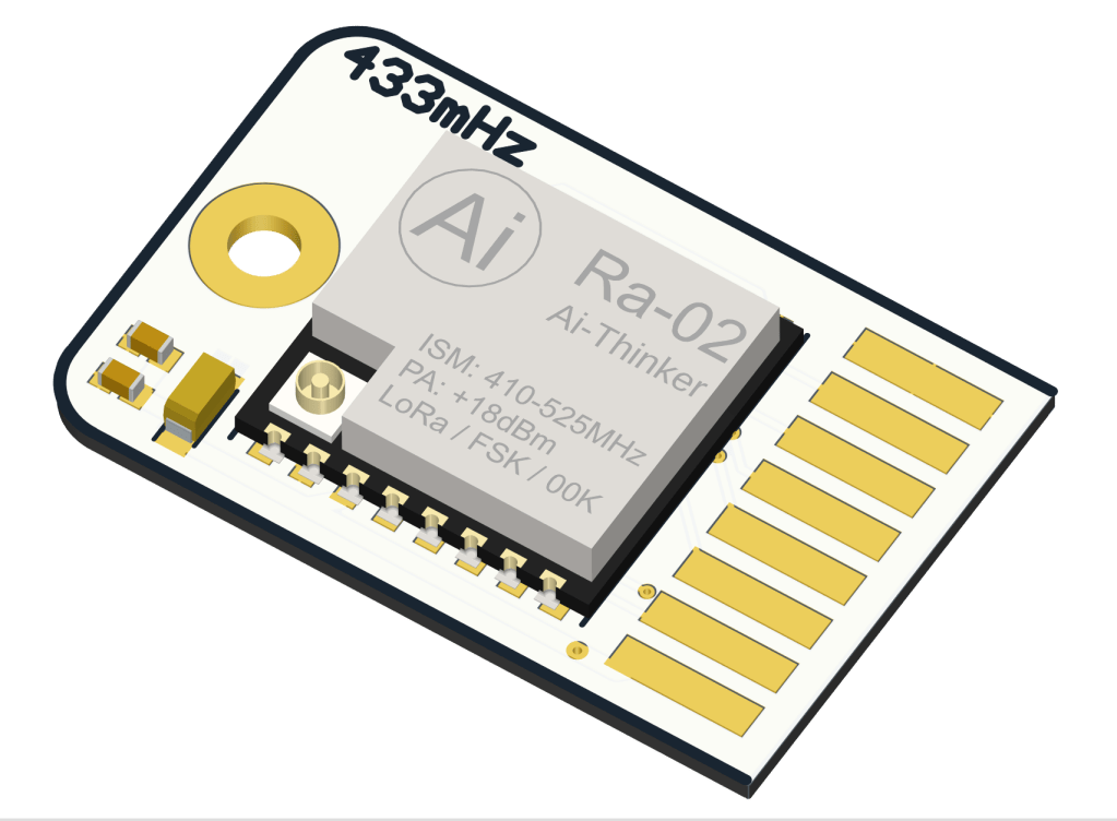
My first task was to make small PCBs that had the 433mHz LoRa module on them, along with a few capacitors, as seen in the first image. These PCBs will later be inserted to the main tower, this method allows the user to insert as many of these modules as they please (up to 10) when setting up the tower. Adding more modules allows for a larger bandwidth for the tower. This also allows for hot swapping of radios incase one fails or if it needs to be quickly removed.
TEST BOARD
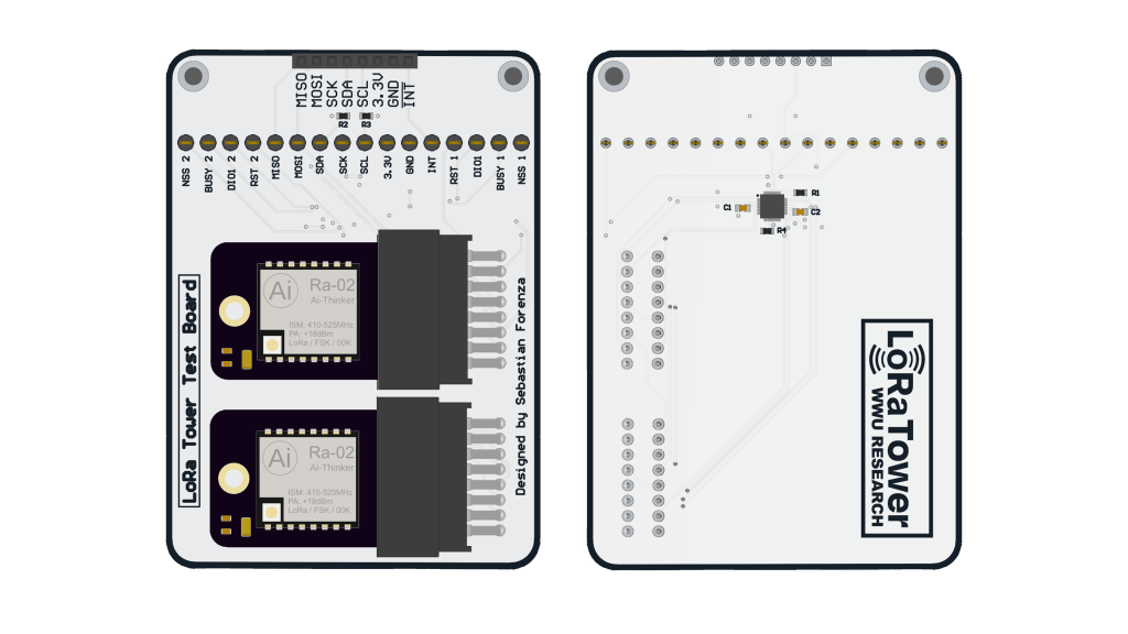
After making the radio modules, I made this test circuit. The purpose of this was basically to just test if the modules worked and if the I2C port expander I found worked in this configuration. After making this board I handed it off to Dr. Lund and he verified that it was fully functional. The port expander was seen on the I2C bus and the radios were fully operational. After seeing that this all worked I spent the next two months carefully designing the final tower
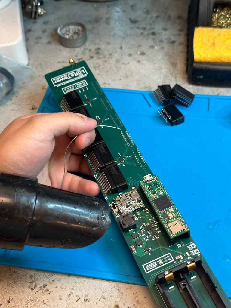
LoRa TOWER BOARD
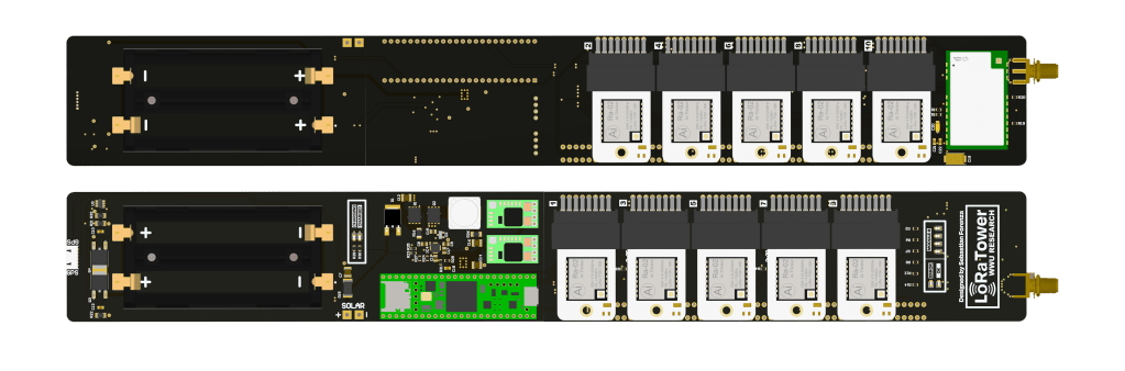
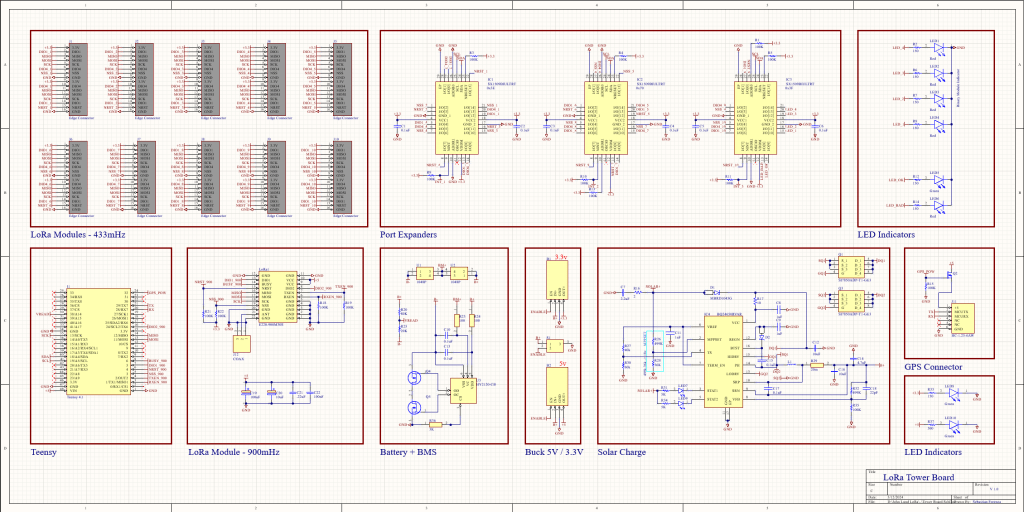
I am really proud of this board, this took me a long time and it came out great. This board holds basically every single part that the tower needs to work (minus the GPS, solar panel and antennas, those have to be separated because of EMI). This board is packed with features, it has 4 battery holders for 18650 cells, along with a 2s BMS to protect the cells from over charging and over discharging. To actually charge the batteries, all that is needed is a solar panel that wires directly to the board. The Solar MPPT circuit on the board gets the most possible power out of the solar panel and then charges the battery pack to 8.4 volts. The battery pack is then wired to two buck converters, a 5V and 3.3V step down. The 5v buck converter powers the Arduino Teensy 4.1, the 900mHz 1W LoRa module, and the GPS. The 3.3v buck converter powers the 10 433mHz LoRa modules, and the port expanders. Antennas can then be hooked up to the LoRa modules and the coax cable at the bottom of the board. All of this fits inside a 2 inch tube, that can then be fixed to a tree, another tower, or the top of a building.
TESTING AND ASSEMBLY
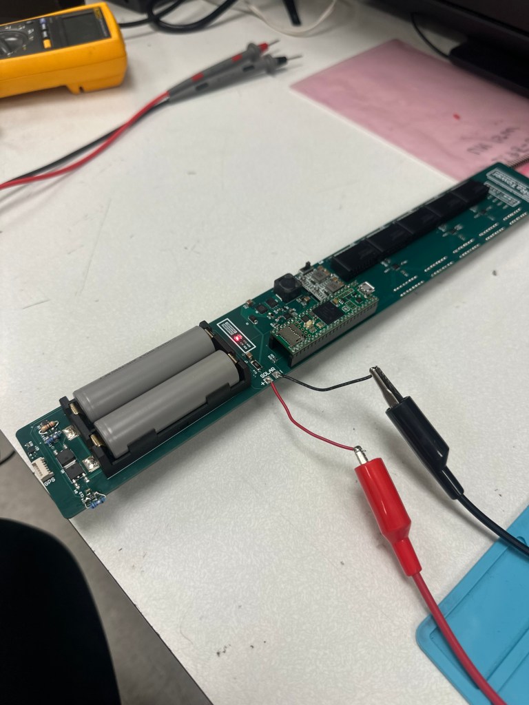

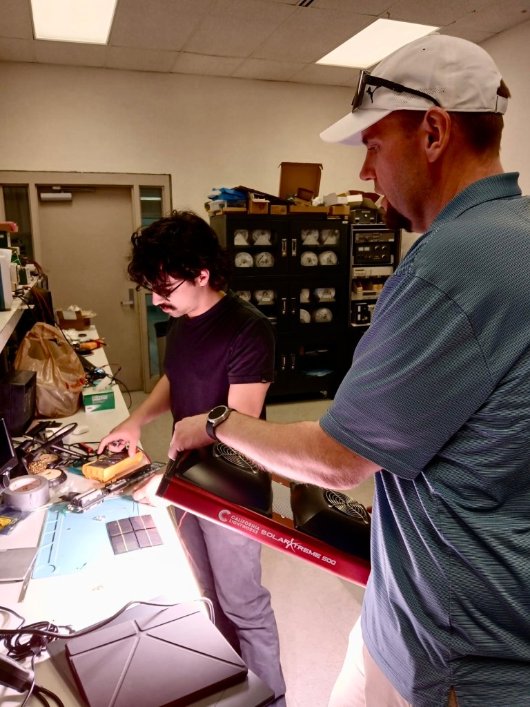
After fully assembling the board, I hooked up the board to a bench power supply to test and see if the solar charge circuit would start charging the cells. To my surprise, the IC I used for the solar charge circuit would not accept a constant voltage from the power supply, it was too smart for that. Instead I rigged up a few solar panels that were laying around the lab, and powered them with a 400W light panel. Once we did that we started to see the circuit accept the power and charge the cells. My professor later tested the circuit with a proper 60W panel and saw better results.