Version 0
8/2023 – 9/2023

INTRO
This is the vehicle control unit (VCU) for this year’s formula car, the Viking 66. I built the schematic off last years VCU that was in very rough shape. This PCB as of right now handles throttle control, brake pressure sensor data, warning lights, and our ready-to-drive (RTD) sequence. This board, along with every other board, is extremely essential to the cars operation. Without this board the car would not be able to move, so it is important that lots of care and planning goes into making this an extremely robust and reliable board for the car.
V64 VCU BOARD
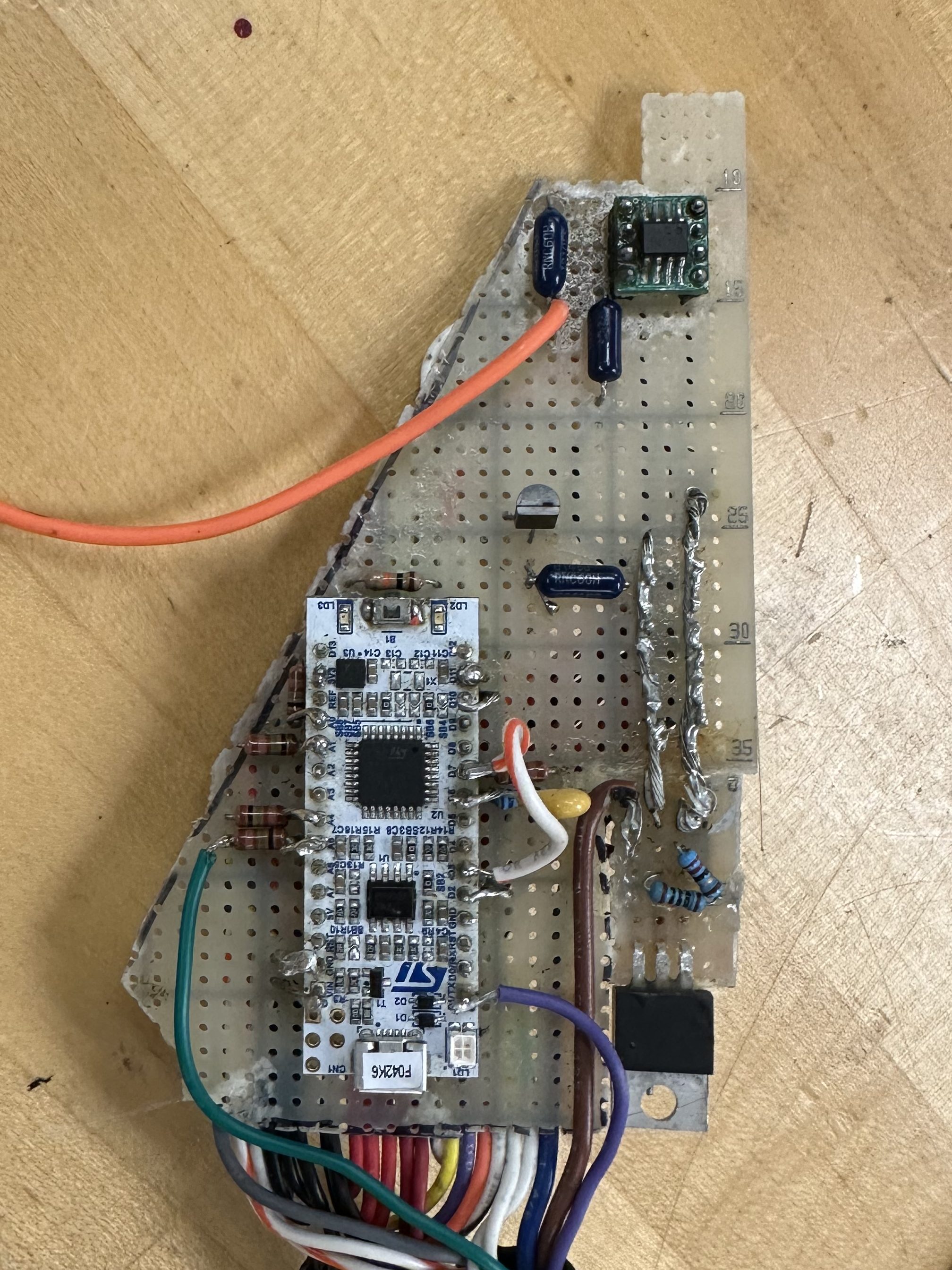
This was the VCU for last years car. The team had experimented with combining PCB’s together to reduce the amount of boards that the car had, and tried combining the VCU with the dashboard PCB of the car. This resulted in EMI issues, along with other problems that went unsolved. In a last ditch effort, and with a shortage of time, the team had made this PCB on perf board in order to make a working VCU for the car. While this board had some parts that worked, like throttle control, it was much too messy to be relied on. Because of loose connections over time and multiple additions of wires and components, the board had lost integrity and has to be made into a proper PCB this year. While this board is a bit messy, I was able to reverse engineer it to the schematic below so we can build off it for V66.
SCHEMATIC

After probing and retracing wires, this is the schematic I created from that board. There are 3 main components to this board, the buzzer circuit, the CAN transceiver, and the linear regulator. The buzzer circuit is responsible for turning on a loud buzzer to indicate the RTD sequence has been completed. The CAN transceiver takes data from the MCU and transmits it to the CAN bus throughout the car for data collection and monitoring. The linear regulator takes 12v in from the battery and creates a steady 5v to power the MCU and other sensors that the VCU is connected to. All of these parts of the board get connected via pads on the PCB that connects to the brake pressure sensor lines, the main VCU line that handles CAN and other data, the accelerator pedal pressure sensor (APPS), and an extra 2 ADC lines for future data lines.
Version 1
10/2023 – 12/2023

CHANGES
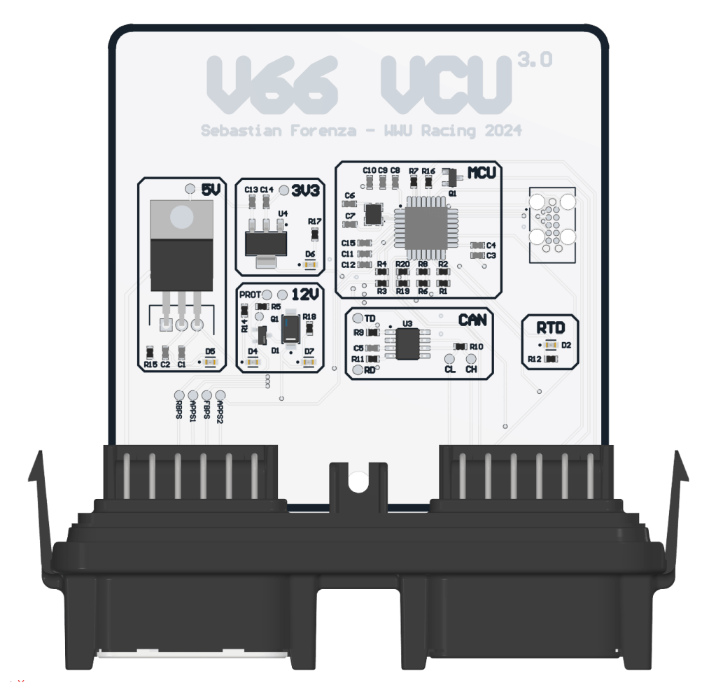
In this new version, the VCU went through a lot of changes. I put the STM32 MCU on the board itself instead of the entire development board, this makes it look more professional and makes for a more complete product. This board also has a proper Deutsch connector on it, making more a more secure connection that will last a lot longer. I also grouped all of the sections of the board into boxes and added indicator LEDs for most boxes to better see if the system is working properly. Along with organization, I added test points all over the circuit so problems could better be diagnosed and save time when testing the board. These changes help new members get a better understanding of the circuit, which allows them to learn faster about the system and make for well-informed teammates.
SCHEMATIC
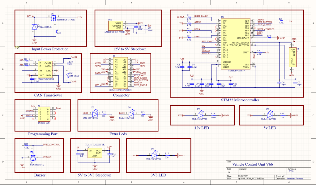
I decided to move away from KiCad for this circuit and moved to Altium for the project, Altium seems to be the standard in the industry and I wanted to get more job experience. I grouped all sections of the circuit into boxes like the PCB to ensure easy look overs by alumni and for new members to easier be able to understand the functional blocks of the circuit.
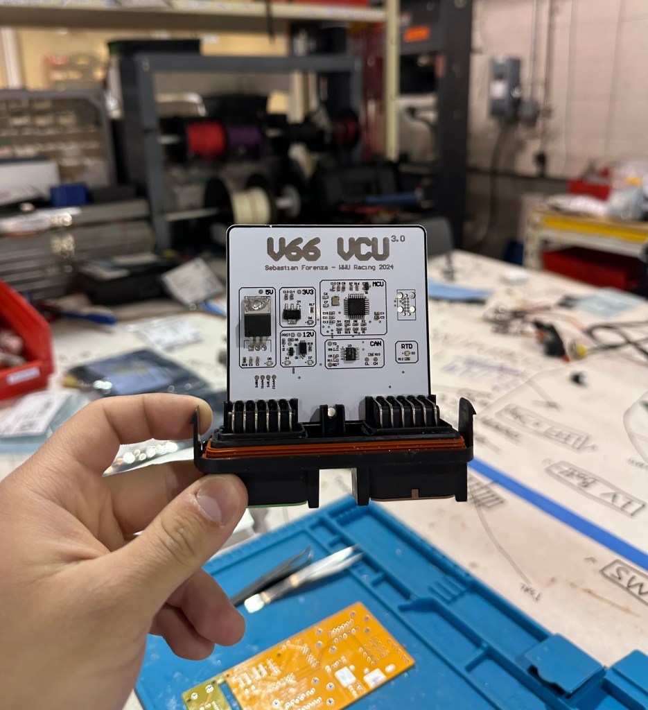
THE BOARD
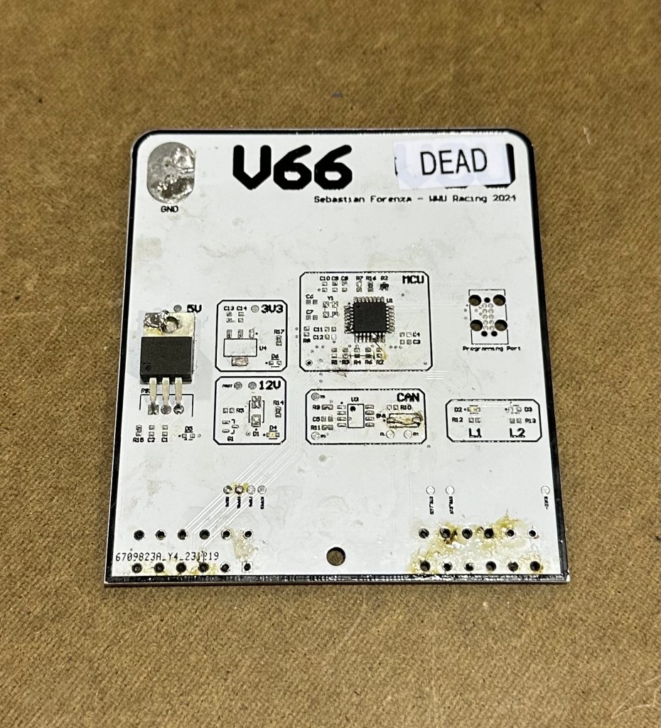
The board looks pretty rough in this picture but its just because it was tested on a lot. Almost everything worked on the board, the only problem was the analog inputs, they were 5V logic when the MCU can only handle 3.3V logic, so it got fried instantly when signals were plugged in. Aside from that, the board was able to be programmed, the power worked, the CAN bus worked. In the next version, all these problems will be fixed.
Version 2
1/2023 – 2/2023
CHANGES
Version 2 has voltage dividers for all analog inputs, this was the most simple and effective solution since it just meant I needed to add 8 resistors to the board. This version worked perfectly, the only problem now was that it didn’t fit in its OEM casing, the tolerances were too tight and the board couldn’t slide in, so I had to make one last board to fix this issue
Version 3
2/2023 – 3/2023
CHANGES
This final board had minimal changes, I made use of some unused pins on the connectors and added extra GPIO pinouts for future additions to the car, I also made the board much smaller so that it could fit inside its OEM housing correctly.
THE END
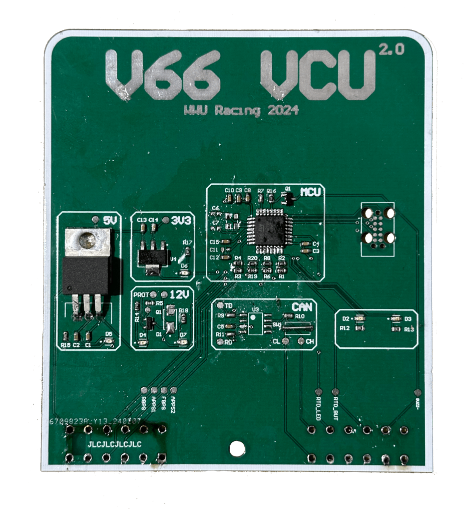
After months of work an iterations, this is the final board. It works flawlessly and functions exactly as needed. This entire project taught me a lot about PCB design techniques, along with integrated circuits, CAN transmission, and much more. This is the final board that will be used in the Viking 66 FSAE Car. I had a lot of fun working on this board and learned a ton about Altium designer along the way. If you made it this far, thank you for reading. More to come very soon!
